|
|
 |
Home>products>Optical Line Monitoring System |
| |
|
|
|
| |
|
Optical line monitoring and management
system
A system which can automatically monitor changes
in loss in working or non-working lines of line networks, compare
and analyze features of the loss, and remotely control measurement
parameters
(1) Composition outline
Line monitoring and composition outline of a management
system
- Manually or automatically measure features of
the optical loss of line networks, detect changes in the loss in advance,
and prevent suspension of communication service
- Find points of failures swiftly, and reduce time of recovery
System composition
|
Division
|
Content |
Notes |
Optical
line Automatic monitoring system
(FiMS-PTP(PTM))
|
-System
which monitors changes in optical loss after automatically
and manually measuring backscattering waveforms of working
optical lines with an optical pulse tester (OTDR).
-Can conduct automatic monitoring, warning, and analysis of
causes, and determine the distance and location of trouble
following changes in the amount of optical electricity due
to the physical transformation of optical lines and environmental
effects.
- Can manage the information of facilities and circuits related
to optical lines.
|
|
| Features |
-
For monitoring wavelength, use 1625 nm (ITU). (1310 nm or
1550 nm may also be selected)
-Structure enables the addition of more optical switch ports
when there is an expansion in the number of target optical
lines.
-Can monitor non-working or working lines.
|
|
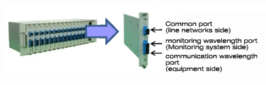
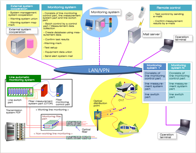
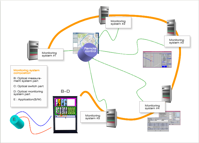
Optical line monitoring and management system equipment
remote control composition
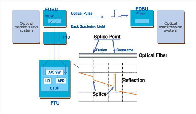
Test principles of working optical lines
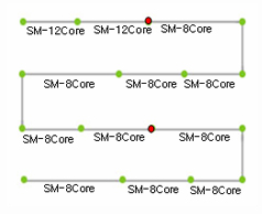
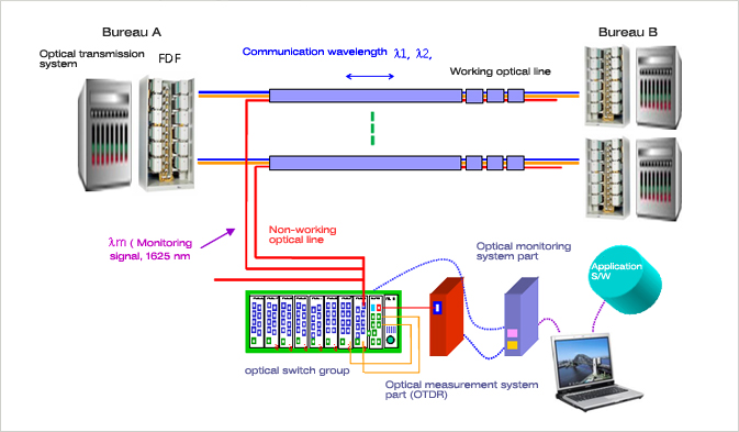
Monitoring system composition at inter-bureau optical
line networks (point-to-point)
Target lines: Optical cable units, non-working optical lines
-Target lines: Optical fiber line unit, working
and non-working lines
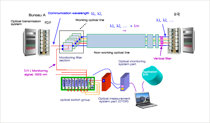
Features of composition
|
System
composition
|
Division |
Contents
|
Note |
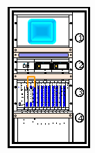
1: Optical monitoring control part (including all types of
module S/W)
2: Fiber optical measurement system part
3: Loose tube optical switch group
4: Optical switch group expansion part / System composition
/ System structure / Expected effects |
System
composition |
H/W
|
Optical
monitoring control part, optical measurement system part,
optical switch section, filter section (working line), cabinet
|
OTDR
measurement |
Backscattering
waveform measurement, measurement environment, etc |
Control |
OTDR,
optical switch, control part, etc. |
Monitoring |
Backscattering waveform and state of loss change, alert |
Analysis and linkage |
application
technique, scheduling, optical line information management,
linkage with systems such as NMS |
| System
structure |
Optical
line network structure, number of monitoring lines and methods,
structure and design determined following switching methods
|
|
Expected effects |
-
Monitor changes in optical fiber loss due to time change of
optical cables and outside factors
-Prevent optical line troubles in advance and reduce recovery
time by swiftly confirming trouble points.
-Prevent optical cable wiretapping by continuously monitoring
changes in optical fiber loss.
- Convenient for medical features of optical fiber, Polarization
Mode Dispersion (PMD), Color Dispersion (CD) feature tests.
|
Optical line monitoring and management system composition
contents (main control part)
|
Composition
|
Division |
Contents
|
Note |
|
Optical
monitoring system part |
Application
of OTDR measurement module, control module, monitoring module,
analyzing and interworking module and others
|
|
|
Optical measurement system part |
OTDR
application (can do preparatory OTDR application) |
|
|
Optical
switch part |
Function
to choose certain lines only, structure enabling expansion,
apply a maximum of 64 ports |
|
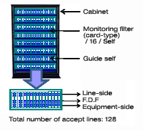
Optical line monitoring and management system composition
contents (monitoring filter section)
|
Composition
|
Division |
Contents
|
Note |
|
Monitoring filter |
Components
adding or dividing communication wavelength and monitoring
wavelength |
|
| Vertical
filter |
Components
blocking only monitoring wavelength at the vertical section
of monitoring optical lines |
|
| Monitoring
filters and vertical filters show one-on-one reactions to lines
to be monitored. |
Monitoring filter section, vertical filter section
composition contents
|
Monitoring
filter |
sectionWavelength
multiplexer
|
Vertical filter section
|
|
|
|
(3) Composition size for each equipment
Necessary facilities and target parts
|
Name
of facilities |
Center
|
Node-1
|
Node-2 |
Node-3 |
Node-4 |
Node-5 |
Total |
Notes |
Management
Server
|
1
|
|
|
|
|
|
1
|
|
Managerment
System |
1
|
1
|
1
|
1
|
1
|
1
|
6 |
|
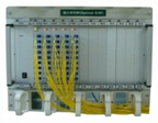
Optical switch part
|
Division |
Content
|
Notes
|
Use
|
System
links a large number of optical lines and selects certain
lines only in order to measure multiple lines with an optical
pulse tester (OTDR). Optical lines to be measured from OTDR
can be physically linked, the linkage and range of optical
lines can be set up regularly, and the movement of optical
switches can be marked and conveyed
|
|
Composition
|
Common part |
|
|
Expected insertion loss |
self, common optical switch, optical switch module |
|
|
Method |
3 dB or less (except optical connecter insertion loss) |
|
|
Insertion loss |
1.5
dB or less (Insertion loss) |
|
|
Reflection loss |
60 dB or more (Return loss) |
|
|
Crosstalk |
60 dB or more |
|
Switching
time |
25 ms or less |
|
Reliability |
10
million
|
|
|
Use temperature |
0~70℃
|
|
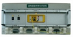
Cabinet part
|
Division |
Content
|
Notes
|
Use |
System
for mounting optical switch sections, optical test sections
and control sections |
|
|
Composition |
Optical
switch section and optical measurement system part, optical
monitoring system part, optical jumper cord, guide panel |
|
|
Structure |
Cabinet-type,
portable structure, back part and side part are sealed. |
|
Size |
1200*600*500
|
|
Optical pulse tester part
|
Division |
Content
|
Notes
|
Use |
-
Device to measure loss of optical lines and distance (access
loss, loss between two points, trouble points, etc.), can judge
obstacles by transmitting measure data from the main server.
-Select optical cables concerned through optical switches, and
conduct manual measurement or automatic measurement according
to the measurement schedules. Mark states of measurement and
data communication and alert situations through monitoring system
LCD and LED.
|
|
|
Composition |
OTDR
module (PCI card-type) |
|
|
Wavelength |
(Wavelength)
1310, 1550, 1625mm
|
|
|
Dynamic range |
42dB/1310nm,
40dB/1550nm, 39dB/1625nm
|
|
|
Light source |
Plused
FP LD, 40mW이상(@25℃) |
|
|
Event dead zone |
3
meter/Event, 10 meter/Attenuation
|
|
Sapling
resolution |
0.25,
0.5, 1.2 meter
|
|
|
Distance accuracy |
+/-5(2.5)meter
per 100km
|
|
|
Pulse |
10ns,
30ns, 100ns, 300ns, 1us, 3us, 10us, 20us, Auto
|
|
Max.
display range |
240km
|
|
|
Standardizing time |
6~600sec
|
|
Management control part
|
Division |
Content
|
Notes
|
|
Use |
Module
conducts networking functions through mutually linking optical
switch part, optical measurement system part and system control
part.
|
|
CPU
|
ARM
9 Processor
|
|
Memory
|
SDRAM
64RAM, NAND FLASH 32M
|
|
I
/ O
|
RS-232,
LAN, USB, JTAG
|
|
OS |
Embedded
Linux Kernel 2.4.18
|
|
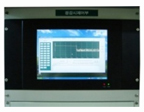
User interface control part
|
Division |
Content
|
Notes
|
|
Use |
Manage
modules of systems, such as an optical switch section, optical
pulse tester and management control part |
|
System
control part
|
Fanless
17” Panel PC (1280X1024)
Intel PentiumM Mobile CPU 1.6Ghz (2M Cache)
Parallel / 5USB / 5RS-232 Port (1RS232/422/485)
Sound / VGA(128M) / 2xLAN(10/100)
17” TFT LCD & Touch Screen
1G DDR2 RAM / 80G HDD(SATA)
Slim CD-ROM / 1PCI Slot
Front USB Port (anti-vibration rubber) / Front (Side) CD-ROM
Anti-vibration, moisture-proof, highly efficient Fan-less Panel
PC
CE / EMI (MIC) certification items |
|
OS
|
WinXP
Pro (Korean)
|
|
Key
/ Mouse
|
Mini
86Key / Mouse
|
|
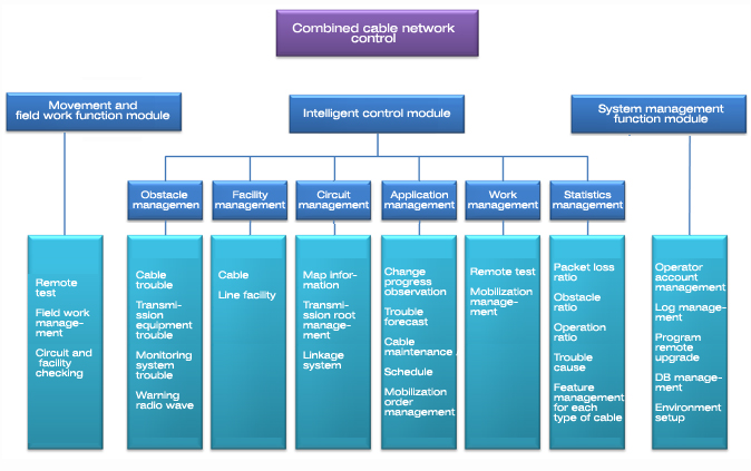
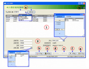
Detailed functions
Combined cable network control module
|
Function |
Screen composition
|
Function explanation
|
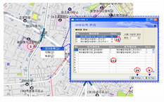
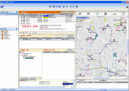
Obstacle
management |
|
-
Current situations of areas in which hazards have occurred
to cables, transmission equipment and monitoring systems,
and the mobilization to recover facilities are shown in real-time.
- After facilities have been recovered, it is possible to
monitor recovery reports.
- There is a function to provide warning via radio waves about
the occurrence of hazards, which can be done through SMS,
visible, audible and other warnings.
|
Facility
management |
|
-
Manage database of optical cable facilities.
- Cables are managed by straight figure.
- Facilities to be managed include cables and line facilities.
|
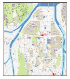
Circuit
management |
|
-
Manage circuits composed by cables linked with transmission
systems among subscribers or among bureaus.
- With automatic information, the locations of a transmission
system and routes of cables linked with it are shown on the
map.
- Linked with other NMS, the information about circuits can
be mutually exchanged.
|
Application
management |
|
-
For daily application management jobs, the regular checking
of cables and line facilities is supported.
- Based on the established data, the change progress of cables
can be observed, and problems can be predicted on this basis.
- By predicting problems, the reliability of communication
lines is improved through the application of preventive measures,
such as changing cables before issues occur, or re-accessing
access points.
|
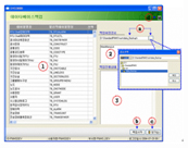
|
Function |
Screen composition
|
Function explanation
|
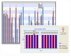
Statistics
management |
|
-
Gather and store collected data by time unit (hour, day, week,
weekday, month) to derive statistical data.
- An operator can define the standards and time for the handling
of data.
- By managing statistics, the packet loss ratio, obstacle
ratio, operation ratio, causes of troubles and feature management
for each type of cable can be understood.
|
Main
screen
|
|
|
|
|
Facility
checking |
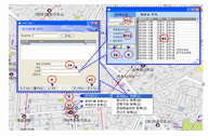
Cable checking
|
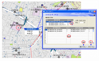
Circuit checking |
We
can check information about the cables and line facilities
that are the targets of management.
|
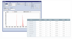
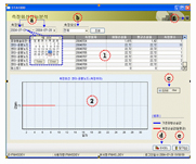
Waveform
analysis |
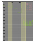
Measurement parameter management
|
Standard waveform
management |
We
analyze the states of optical lines using a certain algorithm
with waveforms derived from the measurement of confirmation
tests or automatic test functions, and report the results.
|
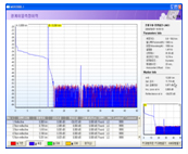
OTDR
EMULATOR
|
2PA Loss measurement
|
Detailed monitoring Location sign |
We
provide a series of functions which measure the states of
optical lines by operating OTDR measuring devices.
|
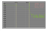
Environment
setup |
Linkage management
|
System management |
We
conduct test schedule management, linkage management, warning
setup, line number sheet management, system management and
distance correction function setup.
|
|
| |
|
|